Polyp Shape Recovery from Single Endoscope Image using Medical Suture
Authors Info & Affiliations
Abstract
Background:
Polyp shapes play an important role in colorectal diagnosis. However, endoscopy images are usually composed of nonrigid objects such as a polyp. Hence, it is challenging for polyp shape recovery. It is demanded to establish a support system of the colorectal diagnosis system based on polyp shape.
Introduction:
Shape from Shading (SFS) is one valuable approach based on photoclinometry for polyp shape recovery. SFS and endoscope image are compatible on the first sight, but there are constraints for applying SFS to endoscope image. Those approaches need some parameters like a depth from the endoscope lens to the surface, and surface reflectance factor . Furthermore, those approaches assume the whole surface which has the same value of for the Lambertian surface.
Methods:
This paper contributes to mitigating constraint for applying SFS to the endoscope image based on a cue from the medical structure. An extracted medical suture is used to estimate parameters, and a method of polyp shape recovery method is proposed using both geometric and photometric constraint equations. Notably, the proposed method realizes polyp shape recovery from a single endoscope image.
Results:
From experiments it was confirmed that the approximate polyp model shape was recovered and the proposed method recovered absolute size and shape of polyp using medical suture information and obtained parameters from a single endoscope image.
Conclusion:
This paper proposed a polyp shape recovery method which mitigated the constraint for applying SFS to the endoscope image using the medical suture. Notably, the proposed method realized polyp shape recovery from a single endoscope image without generating uniform Lambertian reflectance.
1. INTRODUCTION
The endoscope is a medical equipment for diagnosing colorectal polyps. It is used to detect polyps of all sizes, and it allows biopsy of lesions and resection of most polyps [1, 2], and it is considered nowadays as the gold standard for colon screening [3, 4]. There are still open challenges to overcome such as the reduction of the missing rate [5-7]. A polyp guideline for the diagnosis, treatment, and surveillance for patients with colorectal polyps published initially been in 1993 [8] has developed following evidence-based [9-11]. The guideline indicates that the shape and size of a colonic polyp are biomarkers that correlate with its risk of malignancy and guides its clinical management.
The colonic polyp has various shapes depending on its medical condition [12]. Histologically, polyps are classified as neoplastic (adenomas) or nonneoplastic [13, 14]. Neoplastic polyps or adenomas have malignant potential and are classified according to the World Health Organization as tubular, tubulovillous, or villous adenomas, depending on the presence and volume of villous tissue [15]. Increasing dysplasia and, presumably, malignant potential correlate with increasing adenoma size, villous component, and patient age [16] and the likelihood of invasive carcinoma also increase with increasing polyp size [14]. From this perspective of polyp shape and size, the accuracy of polyp measurement is critical for accurate diagnosis [17, 18].
Most small polyps are adenomas with some malignant potential although the likelihood of cancer already existing in a polyp is small (<1%) [19, 20]. Furthermore, hyperplastic polyps, which are common in the lower left colon, have no malignant potential, and several prospective studies have shown that they do not predict an increased prevalence of adenomas in the proximal colon [21-23].
While, advanced adenomas have some characteristics: villous tissue, larger (≥1cm) or appreciable high-grade dysplasia [24]. In a case of the sizeable sessile polyp (>2 cm), it usually contains villous tissue with high malignant potential and tends to recur locally after resection [25], and as the view of the polyp shape, small flat colorectal adenomas are with a purportedly high malignant potential [26].
Computer-Aided Diagnosis (CAD) has been a rapidly growing not only colorectal polyp diagnosis but also various active medical fields of in medical imaging [27, 28]. Polyp detection and classification techniques are mainly developed as CAD for colonoscopy.
Development of these technologies is also underway competition based which provides datasets [29]. As polyp classification techniques, some techniques [30-32] have been developed using a peculiar endoscopic image technology represented by Narrow Band Imaging (NBI) [33, 34] which emphasizes blood vessels. As the polyp detection techniques, various techniques have been developed [35-42]. Especially, some approaches put polyp detection into practice based on shape features [43-45], texture features [46, 47], texture & shape features [48]. Polyp shapes are also important for developing detection technologies.
Hence, it is demanded to establish a supporting colorectal diagnosis system based on polyp shape from the view of the above descriptions.
In computer vision, the techniques to recover shape are called shape from X techniques where X is a key as shading [49-55], stereo [56, 57], motion [58-60], texture [61-63], shadows [64, 65], specularities [66-68], silhouette [69-71], defocus [72-78] etc. Shape from stereo requires a camera which has multiple lenses. However, general endoscopy has a single lens and hardware-based techniques [79-81] requires peculiar endoscope for polyp shape recovery.
There are software techniques to infer the 3D structure of the colon from video sequences such as computational stereo [82], simultaneous localization, mapping [83] and shape from motion [84]. General shape from motion, shadows, specularities assume recovering objects with a rigid structure. However, endoscopy images usually consist of nonrigid objects such as a polyp, and shape from texture requires known texture for the cue of shape recovery so that applying photoclinometry based recovery approach is reasonable for the issue mentioned earlier.
Shape from Shading (SFS) [49] is one valuable approach based on photoclinometry. Since the first SFS technique was developed by Horn in the early 1970s [49], various approaches have been developed [50-55]. SFS uses the intensity of image to recover the surface shape from a single image. Some approaches [85-97] recovered 3D shape from endoscope image based on SFS. Paper [90] proposed a polyp recovery approach using both photometric and geometric constraints assuming one light source endoscope. Another approach [94] recovered polyp shape considering more actual endoscope which has two light sources where the neural network was used to modify the obtained surface gradients. Paper [85] proposed a 3D shape recovery method for an artificial spine except for polyp shape as a target object.
SFS and endoscope image are compatible on the first sight, but there are constraints for applying SFS to endoscope image. Those approaches need some parameters like a depth from the endoscope lens to the surface, and surface reflectance factor . Furthermore, those approaches assume a uniform Lambertian surface with a constant reflectance factor .
This paper contributes to mitigating constraint for applying SFS to the endoscope image based on a cue from the medical structure. An extracted medical suture is used to estimate parameters, and a polyp shape recovery method is proposed using both geometric and photometric constraint equations. It is noted that the proposed method realizes polyp shape recovery from a single endoscope image.
The outline of this paper is as follows. First, the algorithm section introduces an observation system and photometric constraints and describes preprocessing and obtaining parameters approaches for the polyp shape recovery. The experiment section conducted shape recovery using model images and actual endoscope images for the evaluation of the proposed method. Finally, the conclusion section discusses the proposed method with future works.
2. ALGORITHM
The proposed approach assumes an observation system of two light sources endoscope and consists of following steps.
Step 1. Estimate the camera parameters by conducting camera calibration.
Step 2. Conduct specular highlight removal.
Step 3. Generate a Lambertian image for both medical suture region and intestinal-inner-walls.
Step 4. Conduct medical suture segmentation.
Step 5. Obtain depth Z and reflectance factor C using the border between medical sutures and intestinal-inner-walls.
2.1. Observation System of Two Light Sources Endoscope
Some endoscopes used in medical diagnosis have two light sources.
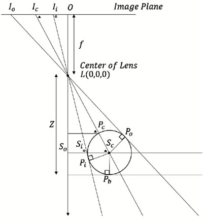
Proposed method assumes an observation system which has a point light source illumination and perspective projection. Fig. (1) shows the observation system of the endoscope with two light sources.
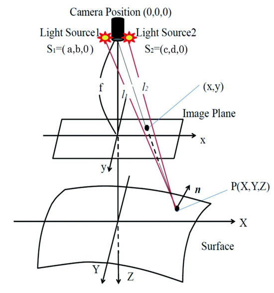
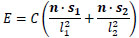
Here, let the coordinate of the center of the lens be (0, 0, 0), let both light source coordinates be s1 = (a, b, 0) and s2 = (c, d, 0), let f be focal length, let each distance from light source to surface be l1 and l2. Let n be the normal surface vector. Image intensity E and reflectance factor C can be denoted as Eq.(1) following inverse square law of illuminance.
 |
(1) |
Eq.(2) represents normal vector n on an arbitrary point of diffuse reflectance surface.
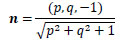 |
(2) |
Here, let p, q be a surface gradient parameters defined by Eq.(3).
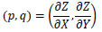 |
(3) |
Let arbitrary surface point be (X, Y, Z), then, Eq.(4) represents l1 and Eq.(5) denotes l2.
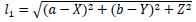 |
(4) |
Eq. (6) and Eq. (7) represent each light source vector s1 and s2 on an arbitrary point of diffuse reflectance surface. Here, let a, b, c and d be each light source coordinates.
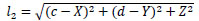 |
(5) |
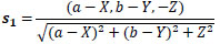 |
(6) |
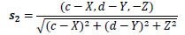 |
(7) |
Eq. (8) represents world coordinate of each X, Y, respectively based on the perspective projection.
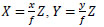 |
(8) |
Substituting Eq.(2) to Eq.(8) into Eq.(1), Eq.(9) gives E using C and Z.
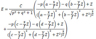 |
(9) |
The proposed method recovers Z distribution from endoscope images postulated in the observation model. This Eq.(9) is used to solve each C of the medical suture and the intestinal-inner-wall (based on Eq.(16) and Eq.(17)).
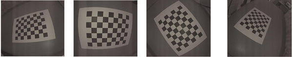
2.2. Camera Calibration
Camera parameters of the endoscope are estimated. Estimating camera parameters of the endoscope is performed using multiple images of checkerboard taken by an endoscope with the existing camera calibration techniques [98, 99]. Fig. (2) shows examples of checkerboard image captured by an endoscope.
Furthermore, a sphere was taken by the endoscope as a known object to estimate each of two light sources coordinates of endoscope s1 = (a, b, 0) and s2 = (c, d, 0).
2.3. Specular Highlight Removal
The product of the spectral energy distribution of the illumination and the surface reflectance represents the spectral energy distribution of the light reflected from the surface. Following the dichromatic reflection model [100], two components of specular and diffuse reflection compose the reflected light. Specular components affect the result of shape recovery under SFS approach and frequently arise on the endoscope image. Paper [101] proposed a method to remove the specular components on endoscope image by conducting the inpainting process to specular components. Modified region by inpainting process lacks the surface information.
The diffuse color component has a characteristic that the maximum fraction of the diffuse color component in diffuse local patches in color images changes smoothly. Hence, specular components can be removed by following this characteristic. Furthermore, the proposed approach obtains depth Z and reflectance factor C based using the border between medical sutures and intestinal-inner-walls. Specular components removal process should be done without removing the border between the medical suture and the intestinal-inner-walls due to the calculation of each reflectance factor C based on the border information. The proposed approach removes specular components by introducing the bilateral filter based on methods [102, 103].
2.4. Generating Lambertian Image
Many approaches have been proposed for the shape recovery assuming Lambertian reflectance as SFS problem. The proposed approach also assumes Lambertian reflectance for shape recovery. Therefore, generating a Lambertian image is conducted for both medical suture region and intestinal-inner-walls.
As generating a Lambertian image method, Paper [104] tries to generate a diffuse component image by removing the specular component by taking images of an object from multiple viewpoints. Paper [105] developed a method to convert the original image to Lambertian image using object rotation. Endoscope environment cannot use the polarizing plate, object rotation and multiple images with different viewpoints for the problem of both camera motion and peristaltic movement of an object inside the body.
So, this paper generates a uniform diffused reflectance surface from the original RGB image for the endoscope image based on method [106]. The approach uses the color clustering with the scalar quantization in RGB space and to treat the same reflectance factor for two neighboring points which locate along the boundary between the different color reflectance factors.
Lambertian image for both medical suture region and intestinal-inner-walls is generated by absorbing the difference of relative reflectance factor and performing near the uniform Lambertian reflectance image for different color reflectance regions of the original image.
2.5. Obtaining Depth Z and Reflectance Factor C
The depth parameter Z and reflectance factor C for shape recovery under SFS approach are obtained by estimating the horizontal plane of medical suture locally considering a horizontal plane in the observation system.
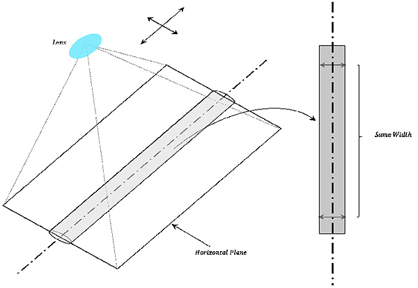
2.5.1. Estimation of The Horizontal Plane
The horizontal planes of columnar forms against lens are derived from assuming the continuity of width from columnar centerline to both ends of the edge. The columnar width cropped by the horizontal plane against lens continues while the cropped region is horizontal against lens as shown in Fig. (3).
The horizontal planes of the medical suture can be obtained locally based on this property. The procedure of obtaining the horizontal plane is as follows.
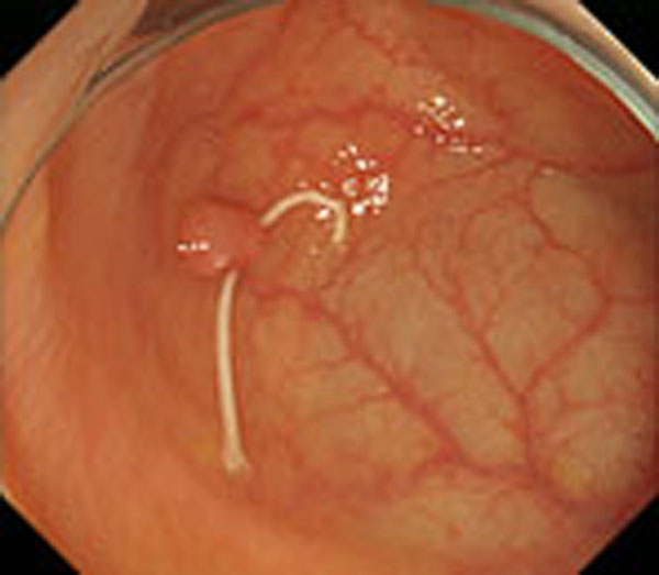
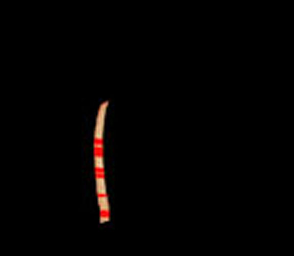
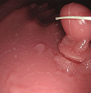
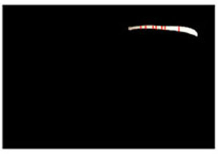
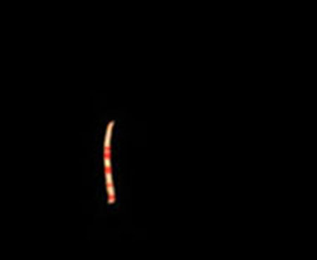
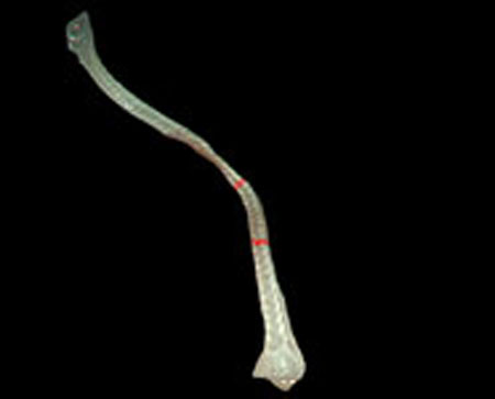
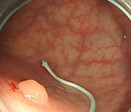
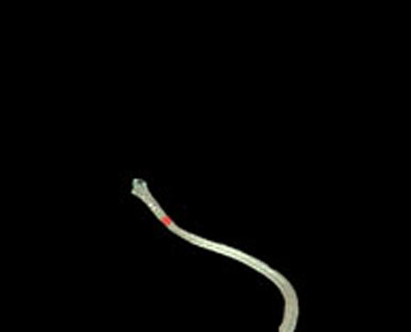
Step 1. Extract medical suture region in Fig. (5) from the original image in Fig. (4).


Step 2. Extract centerline of the medical suture by performing line thinning processing as shown in Fig. (6).
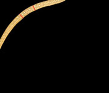
Step 3. Extract edge of medical suture using morphology operation as shown in Fig. (7).

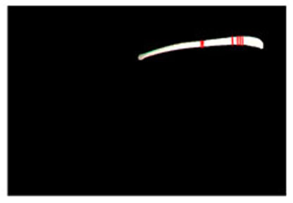
Step 4. Draw an orthogonal line to the centerline and crop the line by both ends of the edge. Finally, extract continuous regions where the cropped line has the same width as shown in Fig. (8).
2.5.2. Estimation of Medical Suture Z and C
Fig. (9) shows an observation model for obtaining depth parameter Z of the medical suture using its horizontal plane.
The depth Z from the endoscope lens can be calculated using the model concerning the estimated horizontal plane of the medical suture. The procedure for calculating parameter Z is as follows.
From Δ LOIi ~ Δ LSoSi and  LSiSc is an external angle of Δ LSoSi, LSiSc is derived from Eq.(10).
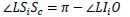 |
(10) |
From Δ LOIc ~ Δ LSoSc from Eq.(11), LScSi can be expressed by Eq.(12).
 |
(11) |
 |
(12) |
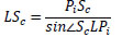
Similarly, LScPi is derived from Eq.(13).
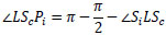 |
(13) |
The hypotenuse from the lens L to the center of the suture center Sc in Δ LScPi, the distance LSc can be obtained from Eq.(14). Here, the distance PcSc is the same as the radius of the medical suture.
 |
(14) |
From Δ LZPc ~ Δ LOIc, the depth Z is derived from Eq.(15).
 |
(15) |
Finally, define F(p, q, a, b, c, d, f, Z) as shown in Eq.(16) using Eq.(9), then, the surface reflectance factor C of intestinal-inner-wall is estimated by optimization using RANSAC [107] and Eq.(17). Here, let p and q be surface gradient parameters, let each light source coordinate be a, b, c, d, let f be the focal length of the lens, let Z be the calculated depth and let Ei be each observed intensity. Besides, let each p and q of intestinal-inner-walls at the neighboring points obtained for the horizontal partitions of the medical suture be zero.
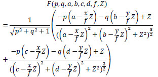 |
(16) |
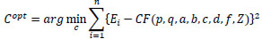 |
(17) |
| Parameters | Result of Calibration |
|---|---|
| Focal Length (pixels) | [718.7447 ± 0.8387, 718.3827 ± 0.8654] |
| Principal Point (pixels) | [879.0439 ± 0.4669, 533.5813 ± 0.4240] |
| Radial Distortion | [-0.3913 ± -0.0010, 0.1178 ± 0.0008] |
3. EXPERIMENT
Experiments were conducted using colon model images and real endoscope images. A medical suture whose diameter is 0.8 mm. Inner parameters of endoscope were obtained from camera calibration. Two light sources coordinates were estimated using a known sphere object with 66 mm diameter.
3.1. Camera Calibration
Table 1 shows the result of camera calibration. Fundamental parameters of the endoscope were obtained by performing camera calibration such as focal length, principal point, and radial distortion. Here, two parameters were obtained respectively based on the aspect ratio of the observed image.
Positions of two light sources on endoscope were estimated using sphere object image as s1 = (a: -5.001 mm, b: 1.996 mm, 0 mm) and s2 = (a: 5.001 mm, b: 1.996 mm, 0 mm).
3.2. Experiment with Model Images
3.2.1. Results of Estimated Depth Z for Model Images
Estimated results for the horizontal plane of the medical suture are as shown in Figs. (10-15), respectively. Here, horizontal plane sections where the same width continues more than 6 pixels tracing the center line of medical suture were adopted as the candidate for a section of the horizontal plane.
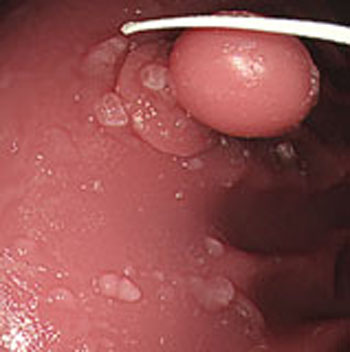
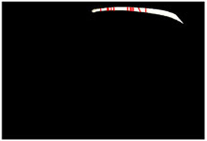
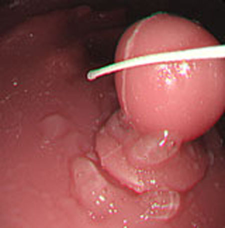
Table 2 shows Estimated MEAN and STD of both Z and C of each scene. Here, each section in each scene means an obtained section of the horizontal plane where the same width continues more than 6 pixels.
From these results, the horizontal section of the medical suture could be obtained within the nm level variation of depth Z in each scene.
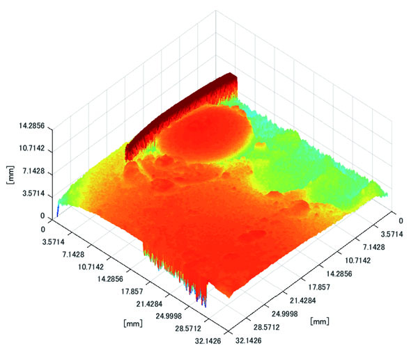
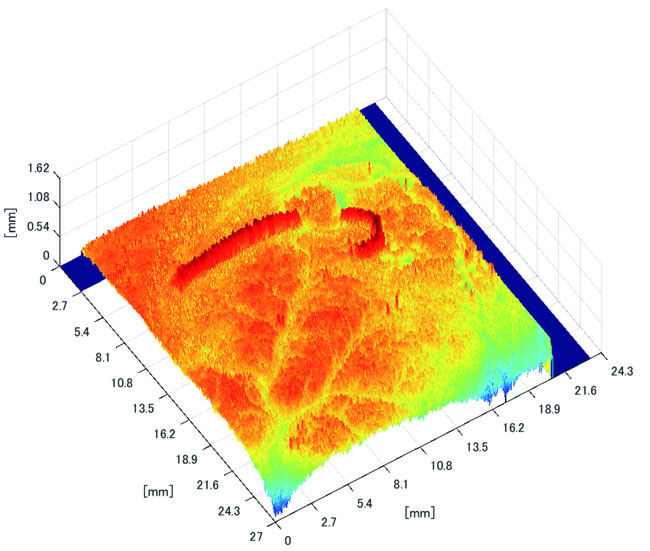
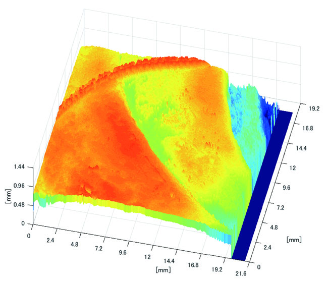
3.2.2. Results of Shape Recovery
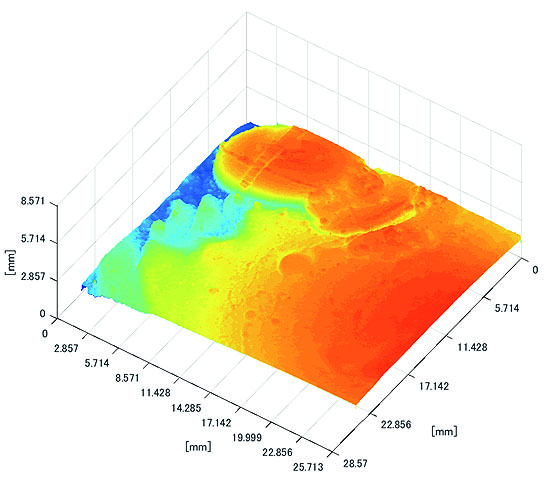
Polyp shape recovery was performed using calculated Z and C. Here, reflectance factor was estimated by the following process. C is estimated in order from the section where the continuous section of the same width region is long as well as with Z less STD is obtained. MEDIAN of C with the low value of STD was selected. Moreover, Smirnov-Grubbs test [108] was applied for outliers where the region has a potential of containing intestinal-inner-wall except for blood vessel. A polyp model whose diameter is about 10mm was used, and some regions were cropped where shape recovery is interfered by a hood cover of the endoscope. Figs. (16-18) show the results of recovered shapes of polyps. From recovered results, it can be confirmed that each polyp shape was recovered with around 10 mm, i.e., the proposed method recovered approximate shape and size using the calculated parameters Z and C.
| Scene | Section | Estimated Z [mm] | Estimated C | ||
|---|---|---|---|---|---|
| MEAN | STD | MEAN | STD | ||
| 1 | 1 | 23.8076 | 0.0000 | 816025.5 | 270.335 |
| 2 | 23.4538 | 0.0000 | 808439.7 | 1618.93 | |
| 3 | 23.4092 | 0.0224 | 809689.3 | 262.500 | |
| 4 | 23.2639 | 0.0000 | 804883.0 | 1840.40 | |
| 5 | 23.0954 | 0.0000 | 797798.0 | 294.000 | |
| 6 | 22.3189 | 0.0000 | 780459.5 | 583.607 | |
| 7 | 22.1798 | 0.0000 | 777842.3 | 600.260 | |
| 8 | 22.0867 | 0.0000 | 775345.3 | 397.500 | |
| 9 | 21.9934 | 0.0000 | 773461.0 | 406.000 | |
| 10 | 21.6174 | 0.0000 | 765179.5 | 310.420 | |
| 11 | 21.2372 | 0.0000 | 758073.0 | 329.512 | |
| 2 | 1 | 23.1742 | 0.0225 | 800335.5 | 1120.31 |
| 2 | 23.0615 | 0.0226 | 797565.0 | 1086.58 | |
| 3 | 21.0095 | 0.0241 | 754426.3 | 1227.83 | |
| 4 | 20.6835 | 0.0280 | 748430.8 | 1333.70 | |
| 5 | 20.5377 | 0.0281 | 746197.8 | 1345.40 | |
| 6 | 20.3790 | 0.0245 | 743103.5 | 1271.01 | |
| 3 | 1 | 22.9145 | 0.0000 | 668735.5 | 4694.48 |
| 2 | 22.3189 | 0.0000 | 647800.0 | 0.00000 | |
| 3 | 22.1333 | 0.0000 | 619218.0 | 10523.2 | |
| 4 | 21.7118 | 0.0000 | 714005.0 | 0.00000 | |
| 5 | 21.4753 | 0.0000 | 706358.5 | 8857.93 | |
| 6 | 20.4157 | 0.0000 | 743463.3 | 583.500 | |
3.3. Experiment with Real Endoscope Images
3.3.1. Results of Estimated Depth Z
Estimated results of the horizontal plane for the medical suture estimation are as shown in Figs. (19-26), respectively. Here, the horizontal plane where the same width continues more than 6 pixels tracing the center line of medical suture were adopted as horizontal plane sections.
Table 3 shows estimated MEAN and STD of both Z and C in each scene.


From these results, horizontal sections of the medical suture were obtained within the nm level variation of depth Z in each scene. These results suggest that the horizontal plane of the medical suture and depth Z was obtained with high accuracy in each endoscope image.
| Scene | Section | Estimated Z [mm] | Estimated C | ||
|---|---|---|---|---|---|
| MEAN | STD | MEAN | STD | ||
| 1 | 1 | 33.8287 | 0.0000 | 1112006.7 | 6757.98 |
| 2 | 33.7345 | 0.0000 | 1147150.0 | 70.7107 | |
| 3 | 33.7206 | 0.0000 | 1077240.0 | 0.00000 | |
| 4 | 33.4927 | 0.0110 | 1062390.0 | 37108.96 | |
| 5 | 33.1182 | 0.0000 | 972636.00 | 10970.88 | |
| 6 | 33.0097 | 0.0000 | 973917.50 | 7732.213 | |
| 2 | 1 | 29.4382 | 0.0184 | 334133.67 | 4460.35 |
| 2 | 29.8657 | 0.0177 | 364612.3 | 8115.47 | |
| 3 | 17.0222 | 0.0000 | 257711.0 | 2964.95 | |
| 4 | 17.0097 | 0.0022 | 296949.0 | 5476.81 | |
| 5 | 16.9246 | 0.0000 | 305874.0 | 8309.92 | |
| 6 | 33.8346 | 0.3201 | 939564.0 | 93865.9 | |
| 7 | 33.1624 | 0.0124 | 1152400 | 20774.8 | |
| 8 | 16.5286 | 0.1686 | 318861.0 | 13696.66 | |
| 3 | 1 | 34.5163 | 0.0031 | 692530.3 | 30117.66 |
| 2 | 34.2091 | 0.0068 | 1118625 | 10175.27 | |
| 4 | 1 | 12.6820 | 3.6753 | 159821.6 | 85942.39 |
| 2 | 15.2671 | 0.0000 | 221748.5 | 2563.262 | |
| 3 | 12.6662 | 3.6783 | 156090.3 | 85166.34 | |
| 4 | 15.1144 | 0.0000 | 226365.0 | 3228.649 | |
| 5 | 15.1002 | 0.0000 | 226979.0 | 3254.105 | |

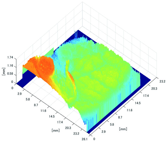
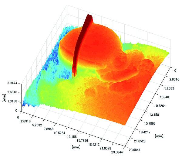
3.3.2. Results of Shape Recovery
Polyp shape recovery was performed using calculated Z and C. Here, C is estimated in order from the section where the continuous section of the same width region is long as well as Z with less STD is obtained. MEDIAN of C with the low value of STD is selected. Moreover, Smirnov-Grubbs test [108] was applied for outliers where the region has a potential of containing blood vessel except for intestinal-inner-wall. Figs. (27-30) shows the results of polyp shape recovery.
Here, some regions were cropped where shape recovery was interfered by a hood cover of the endoscope. From the recovered result, it can be confirmed that approximate polyp shape and size could be recovered using the calculated parameters Z and C.
CONCLUSION
This paper proposed a polyp shape recovery method which mitigated the constraint for applying SFS to the endoscope image using the medical suture. The proposed approach used two light sources endoscope according to the actual environment for polyp shape recovery. Necessary parameters for applying SFS were estimated. The camera inner parameters were obtained by camera calibration, depth Z and reflectance factor C were estimated by using the horizontal plane of the medical suture and its neighboring intestinal-inner-walls. Through experiments, it is confirmed that the approximate polyp model shape and size were recovered using medical suture information and obtained parameters from a single endoscope image. Notably, the proposed method realized polyp shape recovery from a single endoscope image without equalized reflectance factor with Lambertian processing. Applying the proposed method to extend to another reference object (e.g., blood vessel) remains as future work.
ETHICS APPROVAL AND CONSENT TO PARTICIPATE
Not applicable.
HUMAN AND ANIMAL RIGHTS
No Animals/Humans were used for studies that are basis of this research.
CONSENT FOR PUBLICATION
Not applicable.
CONFLICT OF INTEREST
The authors declare no conflict of interest, financial or otherwise.
ACKNOWLEDGEMENTS
This research is supported by JSPS Grant-in-Aid for Scientific Research (C) (17K00252) and Chubu University Grant.